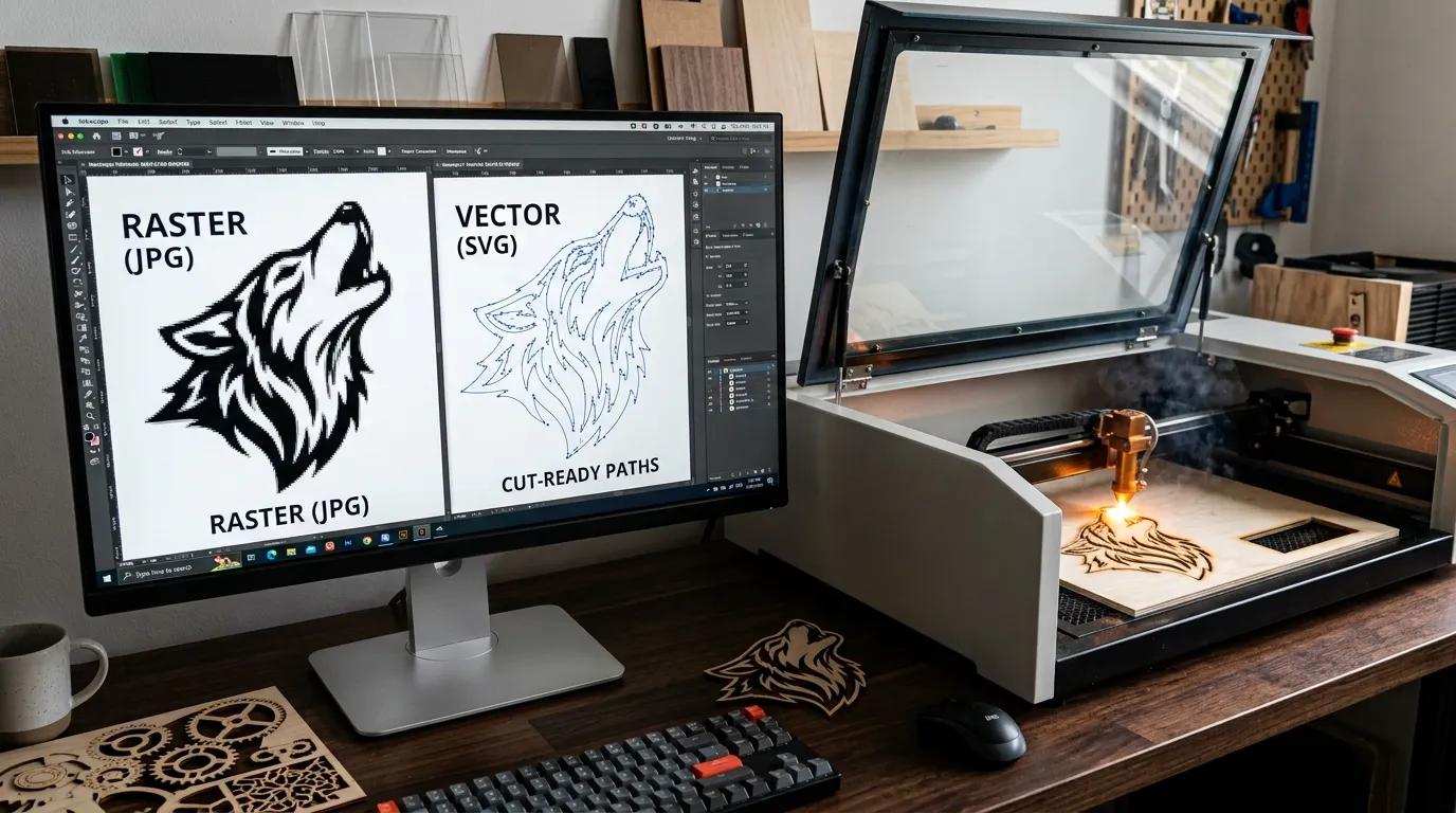
Before a machine moves, I judge the file by its cut-ready geometry, not its appearance. A polished raster image may hide pixelation, while disciplined vector paths reveal whether laser cutting will remain accurate at scale.
From experience, reliable results begin with path continuity, sensible node reduction, and deliberate cut order. These choices matter more than flashy software because closed contours and clean outlines prevent hesitation, duplicate passes, and wasted material.
Modern automatic tracing is useful, yet I still inspect anchor points, remove stray points, and confirm physical scale. That practical review turns convenient vector output into dependable instructions for repeatable production across varied laser machines. If you’re new to stencil-specific vector work, our Stencil Making Tools & Techniques: Complete Guide is a good companion piece to this one.
Quick summary: Laser cutters read mathematical paths, not pixels, so raster images (JPG, PNG, TIFF) must be converted — or “traced” — into vector formats (SVG, DXF, AI, EPS) before a machine can cut them. Clean, closed, cut-ready paths with the right node count are what separate an accurate cut from a jammed, double-cut, or distorted one.
Raster Images vs. Vector Images
For production, vector files usually outperform a pixel-based image because scalable geometry, sharp edges, and accurate paths remain stable at any size, while resolution dependence can turn enlarged raster artwork visibly uneven during cutting operations.
In my laser workflow, a bitmap image is useful for raster engraving, photographs, or tonal texture; however, a vector image gives the controller cutting instructions directly through editable paths, lines, curves, and clearly defined boundaries.
The practical distinction appears during editing: raster artwork depends on a pixel grid and colored squares, whereas vectors use points, mathematical shapes, and smooth curves, allowing geometry modification without rebuilding the original design from scratch.
Yet vectors are not automatically cut-ready. An embedded raster image inside a PDF or SVG may imitate a vector container, so I apply an enlargement test, inspect nodes, and confirm object selection before production begins safely.
Choose raster when surface shading matters; choose vectors when the laser must follow continuous contours for clean cutting. With path closure, closed paths, and no open endpoints, the machine delivers predictable cuts consistently and reliably.
Why Laser Cutters Need Vector Files
Laser cutters require vector files because they operate through path following instead of reading individual pixels like raster images. Vector graphics contain vector contours, vector lines, and mathematical instructions that help machines create accurate cutting results.
Unlike pixel-based designs, vector files provide exact paths with clear start points and stop points. This allows the laser machine to move smoothly along defined shapes while maintaining mathematical accuracy and producing repeatable cuts across different materials.
The major advantage of vector files is their scalability. A design can be enlarged or reduced without losing quality because the machine follows calculated geometry rather than depending on fixed-resolution images.
For professional manufacturing, laser cutting depends on reliable digital instructions. Proper vector contours help reduce errors, improve workflow efficiency, and ensure the final product matches the original design with consistent precision.
Supported Raster and Vector File Formats
Laser cutting projects require proper file compatibility because different machines and software systems accept specific input formats and output formats. Understanding the difference between raster formats and vector formats helps users prepare designs correctly for manufacturing.
Vector containers store scalable design information such as paths, curves, and shapes that can be interpreted by laser software. Common vector file formats are designed to maintain machine-specific output requirements while preserving editable geometry.
On the other hand, raster formats contain pixel-based image data and are often used as image inputs before conversion. Files with different file extensions may include embedded information that affects how software reads and processes the artwork.
Choosing the correct format improves format compatibility between design applications and cutting machines. A suitable file structure ensures smoother workflow, accurate processing, and better results during laser cutting operations.
Common Raster Inputs
Common raster inputs used in laser-cutting workflows include:
- JPG / JPEG
- PNG
- BMP
- TIFF
- GIF
A typical raster upload may contain logos, sketches, photographs, or scanned artwork that needs to be converted into vector geometry. The quality of the original bitmap input strongly influences how accurately the final traced paths are created.
Formats such as PNG and TIFF can preserve cleaner image details, while JPG and JPEG files may contain compression that affects edge clarity. For better vectorization, high-contrast and clearly defined raster artwork usually produces more accurate results.
Before importing a raster file into laser software, users should check its resolution, contrast, and overall image quality. A clean image import makes tracing easier and reduces unnecessary cleanup after the conversion process.
Common Vector Outputs
After raster artwork is converted, the final design is usually saved in one of these common vector output formats:
- SVG (Scalable Vector Graphics)
- DXF (Drawing Exchange Format)
- EPS (Encapsulated PostScript)
- AI (Adobe Illustrator)
- DWG (AutoCAD Drawing)
- G-code, in workflows that need direct machine movement instructions
These formats preserve clean geometry and precise cutting information. Formats like DXF, DWG, and AI are widely used for editable geometry, while SVG and EPS help maintain design quality across different sizes. They are useful when further editing or production adjustments are required.
For laser manufacturing, the exported file should contain clearly defined cutting paths that the machine can follow accurately. In some workflows, designs are converted into machine-specific G-code to provide direct movement instructions to the laser controller.
Choosing the right vector export format depends on the software, controller, and cutting system being used. A properly prepared file improves compatibility, preserves geometry, and reduces errors during final laser production.
How to Convert an Image to Vector for Laser Cutting
The conversion process usually follows the same sequence regardless of which software you use:
- Preprocess the image. Improve brightness, contrast, and background removal on the original raster photo, logo, sketch, or drawing so the important edges remain clearly visible.
- Import and trace. Bring the image into suitable software and run an automatic trace feature — such as Image Trace, PowerTRACE, Potrace, or bitmap trace — which relies on edge detection and threshold adjustment to create initial vector paths.
- Clean up the result. Automatic tracing often produces excess nodes, double lines, or open paths. Use simplify paths, manual pen-tool tracing, or a manual redraw where needed, then close shapes, merge shapes, or unite shapes to create clean geometry.
- Verify before export. Perform layer verification and scale verification inside your laser software.
- Export. Save the cleaned file through SVG export, DXF export, EPS export, or AI export, depending on the machine and workflow requirements.
If you’re starting from a plain PNG and want a more beginner-focused, step-by-step version of this same process, our PNG to SVG Conversion for Stencils guide walks through it in more detail.
Recommended Software and Tools
Choosing the right software and tools makes vector preparation faster and more accurate.
Vector editors: Popular options include Adobe Illustrator (Image Trace),CorelDRAW (PowerTRACE),Inkscape, Corel Vector, and other vector editor platforms designed for creating and refining laser-ready paths. If you’re building stencil artwork specifically rather than general laser-cut parts, our Illustrator Stencil Design Guide covers the stencil-specific workflow, including bridges and cut-ready outlines.
CAD software: For technical drawings and engineering work, AutoCAD, SolidWorks, Fusion, Onshape, and FreeCAD (a free, open-source option) provide powerful CAD features. These programs are especially useful when precise dimensions, mechanical shapes, or production-ready geometry are required.
Image preparation: Photoshop or GIMP can help with image editing before tracing. Cleaning backgrounds, improving contrast, and sharpening important edges can significantly improve the quality of professional tracing and final vector conversion. Our Photoshop Stencil Making Tutorial covers this preprocessing stage step by step.
Machine operation: Tools such as LightBurn, other laser control software, and machine-specific laser software help import vector files, assign cutting settings, and send jobs to the laser cutter. Users may also use online raster-to-vector converters or a free vector editor for simpler projects.
Vector Cleanup and Optimization Settings
Proper cleanup settings are essential after tracing because automatically generated vectors may contain rough edges, unnecessary details, or inefficient paths. Adjusting vector optimization settings helps produce cleaner geometry that is easier for laser software to process.
Use threshold tuning, spot removal, and smoothing to eliminate jagged edges, unwanted marks, and excessive small details. These adjustments improve path quality while preserving the important shapes needed for accurate cutting or engraving.
For complex designs, path optimization and travel optimization can reduce unnecessary machine movement and simplify the toolpath. Lowering excessive segments also helps control G-code complexity and improves overall cutting efficiency.
Additional options such as downsampling, adaptive quality, and filling can simplify detailed images while maintaining useful visual information. Balanced optimization creates cleaner vectors, faster processing, and more reliable results without removing important design features.
Spot Removal
Spot removal is used to clean unwanted elements that appear after tracing a raster image. These may include tiny spots, random marks, whiskers, or other forms of graphical noise that create unnecessary vector paths.
During vector cleanup, remove small unwanted paths and obvious trace artifacts that do not belong to the original design. This keeps the artwork cleaner and prevents the laser from following meaningless lines during cutting or engraving.
Care should be taken with aggressive removal, because automatic cleanup can sometimes delete important small details along with unwanted elements. Fine logos, text, or decorative patterns may contain tiny shapes that are essential to the final appearance.
A controlled spot-removal process eliminates unwanted marks while preserving useful geometry. Reviewing the vector after cleanup helps ensure that only unnecessary artifacts are removed and all important design details remain intact.
Smoothing
Smoothing helps improve traced vector artwork by reducing rough or jagged edges created during automatic conversion. It makes irregular outlines cleaner and produces more natural, smooth contours that are easier for laser machines to follow.
Applying path smoothing can transform sharp traced edges into softer curves without changing the main shape of the design. This is especially useful for logos, illustrations, and artwork containing curved or rounded elements.
Proper curve refinement improves overall trace quality while keeping the design visually accurate. However, excessive smoothing should be avoided because it may remove fine details or slightly alter important contours within the original artwork.
A balanced amount of edge cleanup creates cleaner vector paths and improves cutting consistency. The goal is to remove unnecessary irregularities while preserving the important geometry required for accurate laser cutting and engraving.
Path Optimization
Path optimization improves the efficiency of vector artwork by simplifying unnecessary segments and organizing the geometry into cleaner cutting routes. A well-optimized file allows the laser machine to follow detected paths with fewer interruptions and smoother movement.
Reducing excessive segments through path simplification lowers overall file complexity while keeping the original shape accurate. This also improves node efficiency, making the vector easier to edit, process, and prepare for production.
Efficient, optimized geometry can also reduce G-code complexity, which helps the laser controller process instructions more effectively. Cleaner paths often result in steadier machine movement and more consistent cutting performance across detailed designs.
Good optimization balances simplicity with accuracy. Removing unnecessary points without damaging the design improves cutting performance, keeps the vector manageable, and creates a cleaner toolpath for reliable laser cutting.
Downsampling
Downsampling reduces the resolution of overly detailed raster images before vectorization. This process helps simplify visual information so the tracing software focuses on important shapes instead of converting every tiny pixel variation into unnecessary paths.
For high-resolution images, excessive detail can create jagged edges, stains, and numerous insignificant marks during tracing. Applying controlled resolution reduction makes the source image cleaner and easier to convert into useful vector geometry.
Effective image simplification and detail reduction can significantly improve trace cleanup by preventing unnecessary nodes and complicated contours. This is especially useful when the original artwork contains textures or details that are not required for laser cutting.
Downsampling should be applied carefully because excessive reduction may remove important design features. The goal is to simplify overly detailed images enough to achieve cleaner paths while preserving the shapes and details needed for accurate laser production.
Adaptive Quality
Adaptive quality automatically adjusts vectorization detail according to the size and complexity of a design. This adaptive processing approach helps maintain useful geometry without creating unnecessary paths that can slow down laser preparation.
For small jobs, the system may apply detail increase so fine features remain visible after tracing. This improves overall trace quality when working with compact logos, symbols, lettering, or other designs containing delicate elements.
For large designs, detail limitation can prevent excessive nodes and overly complex contours. This form of size-aware optimization keeps the vector file manageable while preserving the important structure needed for accurate cutting and engraving.
The ideal settings depend on the overall design scale and intended output. Balanced adaptive processing improves efficiency, maintains consistent quality, and ensures that both small and large laser projects contain an appropriate level of vector detail.
Filling
Filling determines how the interior area of a vector shape is processed during laser work. A vector fill or raster fill can be applied when the project requires solid areas instead of only cutting along an outer contour.
An outline trace normally follows the boundaries of a shape, while a fill pass processes its internal area. This distinction becomes important when preparing artwork that combines cutting with surface engraving.
For filled shapes and solid regions, suitable fill settings help the laser process the entire selected area consistently. These settings are especially useful when creating logos, text, decorative patterns, or graphics requiring an engraving fill.
Before production, confirm whether each object requires an outline or filled operation. Correct filling prevents unnecessary processing and produces cleaner engraved areas while preserving the intended vector geometry.
Node Reduction
Node reduction simplifies vector paths by removing unnecessary nodes that do not contribute meaningfully to the shape. Excessive anchor points can increase file size, complicate editing, and make laser-processing instructions unnecessarily complex.
A high node count often appears after automatic tracing, particularly around curved or irregular edges. Applying controlled node cleanup improves path simplification while maintaining the important geometry of the original design.
Cleaner paths provide better editing efficiency and easier file handling because designers can modify curves without managing hundreds of unnecessary points. Proper geometry optimization also creates smoother instructions for laser software.
Effective node reduction improves cutting efficiency without sacrificing shape accuracy. The objective is to retain enough points to define the design precisely while removing redundant information from the vector file.
How to Check Whether a File Is Really Vector
A file extension alone does not guarantee that artwork is truly vector. Some container formats such as EPS can still contain embedded raster images, so the actual contents should be inspected before laser production.
One simple method is the zoom test. Open the artwork in a vector editor and enlarge it significantly. Genuine vector paths remain smooth, while raster content usually develops visible pixelated edges.
For stronger vector verification, select individual objects and check whether their paths, nodes, and shapes can be edited independently. If the image behaves like one fixed bitmap, it may still contain raster information.
Always inspect both the file extension and internal artwork structure before cutting. Proper verification prevents a fake or embedded raster file from causing tracing problems later in the workflow.
Preparing a Vector File for Laser Cutting
Good preflight preparation begins by removing unnecessary objects, checking open contours, and eliminating duplicate lines that could cause repeated cutting. Every important shape should be inspected before sending the design to production.
Separate cut layers and engrave layers so different operations can receive appropriate machine settings. Proper layer separation keeps cutting and engraving instructions organized and reduces production errors.
Convert text into text outlines or text paths to avoid missing-font problems. Designs containing floating internal sections may also require bridges or a stencilized design so enclosed pieces remain connected after cutting.
Finally, verify external outlines, internal paths, merged shapes, united shapes, and unnecessary nodes before saving the project in an accepted vector format.
Common Vectorization Mistakes
A major mistake is trusting one-click conversion or automatic trace results without reviewing the output. Automatic tools can create double lines, duplicate paths, broken paths, and open paths that cause incorrect machine movement.
Another problem is missing cleanup. Traced raster line edges may produce too many nodes or unnecessary contours, leading to multiple cuts, increased processing time, and visible imperfections in the finished product.
Both excessive smoothing and excessive spot removal can cause small detail loss. Complex photographs may also require a manual redraw because automatic conversion cannot always interpret complicated visual information accurately.
A fake vector file can create further workflow confusion, especially when raster artwork is simply embedded inside a vector container. Careful inspection and manual correction help prevent these common path errors.
Fully Automatic Vectorization
Fully automatic vectorization uses software-driven image analysis to identify shapes and convert raster information into paths without requiring extensive manual tracing. If you’d rather skip desktop software entirely for a first pass, our own Free Stencil Maker Pro Online does this kind of automatic image-to-outline conversion directly in your browser.
Through one-click tracing, the software performs automatic path generation based on detected image boundaries. This approach can make basic raster conversion faster for simple artwork.
The effectiveness of trace automation depends heavily on image clarity and complexity. Clean logos, silhouettes, and high-contrast graphics usually produce stronger results than detailed photographs.
Even when automatic vectorization creates a usable starting point, inspecting the generated paths remains important because automatic systems may still introduce unnecessary shapes or inaccurate contours.
Sub-Pixel Precision
Sub-pixel precision improves tracing by estimating edges more accurately than simply following visible pixel boundaries. This allows conversion software to generate smoother and more precise geometry from raster artwork.
With effective high-resolution tracing, the software can calculate accurate edges between neighboring pixels instead of producing rough staircase-like contours.
This higher level of edge accuracy is particularly valuable when artwork contains fine detail or curved shapes requiring precise vector paths.
Sub-pixel methods can therefore improve the accuracy of vectorized artwork while reducing visible irregularities caused by the fixed pixel structure of raster images.
The Right Number of Nodes
The ideal node count provides enough control to maintain path accuracy without making the vector unnecessarily complicated. Too many nodes can make editing difficult and increase processing requirements.
Using optimized nodes improves path simplicity and allows curves to remain smooth while reducing unnecessary points generated during tracing.
A manageable number of nodes also improves curve control because designers can adjust editable curves more easily without dealing with excessive anchor points.
Good node management creates a balance between file efficiency and design accuracy, producing geometry that remains both easy to edit and suitable for laser production.
Edit the Result
Automatic tracing should normally be followed by vector editing so the generated design can be inspected and improved before production.
Use node editing, path correction, and shape adjustment to repair inaccurate curves, misaligned edges, or unwanted geometry created during conversion.
When necessary, perform manual cleanup and geometry correction on individual sections rather than relying entirely on automatic processing.
The goal of result refinement is to create an editable output that accurately represents the intended artwork while remaining clean enough for reliable laser cutting.
Tracing, Not Embedding
True vector conversion requires real tracing and path generation, not simply placing a bitmap inside a vector file container.
With raster embedding, the original pixels remain inside the file even though its extension may appear to represent a vector format. An embedded raster therefore does not provide genuine vector geometry.
A true vector conversion replaces image boundaries with paths, curves, and shapes that create editable geometry.
Proper tracing produces scalable output that can be resized, edited, and processed by compatible laser software without depending on the original raster resolution.
Vectorize Artwork and Logos
Vector artwork is particularly useful for logos, illustrations, and other graphics that need clean shapes and consistent proportions.
During logo tracing, individual color shapes can be converted into editable paths, allowing designers to refine edges or modify individual elements independently.
Proper vectorization turns ordinary artwork and brand graphics into scalable graphics that remain sharp when resized for different applications.
This makes vector conversion especially valuable when the same logo or graphic needs to be used across small products, signs, panels, and larger laser-cut designs.
Trace Photos
Photo tracing is more challenging than converting simple logos because photographs contain more image detail, gradients, textures, and irregular color regions.
Successful photo conversion often requires simplification before tracing so the software can focus on important shapes instead of attempting to reproduce every visual variation.
Effective contour detection can separate major subjects and boundaries, but complex images may still produce a large number of paths.
Because vectorized photographs can become highly detailed, reducing unnecessary information usually produces cleaner artwork that is easier to prepare for laser cutting or engraving.
Vectorize Scans
Scanned images such as sketches, drawings, or documents often require preparation before vector conversion because scanning can introduce noise and uneven backgrounds.
Performing scan cleanup helps remove background noise while making important outlines easier for tracing software to detect.
Clear line art and sketch scans generally convert more successfully than complex photographic scans because their boundaries are easier to identify.
Whether working with raster scans or document scans, cleaning the source first usually creates smoother vector paths and reduces unnecessary editing after conversion.
Image Type, Detail Level, Quality, and Color Settings
Effective vectorization depends on choosing the correct image type, detail level, and color settings before tracing begins.
Simple artwork can often use fewer colors and lower complexity, while detailed images may require carefully adjusted quality settings, edge detail, and color count.
These vectorization controls influence how the software interprets image complexity and determines which visual information should become vector geometry.
Balancing the trace configuration with the intended output quality helps avoid both excessive detail and oversimplification in the final vector file.
Upload Limitations and Browser Compatibility
Online conversion tools may impose upload limits based on file size, image dimensions, or the number of files that can be processed.
These input limitations and processing restrictions should be checked before using a browser-based vectorization platform, particularly for large or high-resolution artwork.
Browser compatibility can also affect web upload functionality. Some services work more reliably with specific supported browsers or updated browser versions.
Before relying on online conversion, confirm the platform’s technical limits so unexpected upload failures do not interrupt the vectorization workflow.
Seven Types of Vector Files
Different vector file types are designed for different design, engineering, and manufacturing workflows. Here are seven of the vector formats laser-cutting projects run into most often:
- AI (Adobe Illustrator) — a native, fully editable format built around Illustrator’s path and layer structure; the default working file for most Illustrator-based design work.
- EPS (Encapsulated PostScript) — an older, widely supported vector format that many legacy design and print workflows still request because almost every vector application can open it.
- SVG(Scalable Vector Graphics) — an XML-based, web-native format that has become a common bridge between browser-based tools, design apps, and laser software.
- PDF (Portable Document Format) — can store vector paths losslessly alongside text and raster elements, making it a convenient way to share a design without requiring the original design software.
- DXF(Drawing Exchange Format) — a CAD-oriented format built for exchanging precise geometry between AutoCAD-style programs and manufacturing software; one of the formats laser controllers expect most often.
- DWG (AutoCAD Drawing) — AutoCAD’s native drawing format, closely related to DXF but less universally supported outside CAD applications.
- CDR (CorelDRAW) — CorelDRAW’s native file format, common wherever PowerTRACE and Corel’s design tools are already part of the workflow.
The most appropriate format depends on design software compatibility and the requirements of the software or machine receiving the artwork. Some formats focus on graphic design, while others are commonly associated with CAD and manufacturing formats used for technical geometry. Understanding these format differences helps designers select a file type that preserves important information and transfers smoothly between applications.
Benefits of Vector Files for Laser Cutting
One of the major advantages of vector artwork is machine readability. Clean paths provide clear geometric instructions that laser software can interpret accurately.
Because vectors are based on mathematical geometry, designs maintain their proportions and sharpness regardless of how much they are resized — see our guide on how to scale a stencil without losing quality for a closer look at exactly what this means in practice.
This scalability makes a single design suitable for both small and large production applications without recreating the artwork.
Vector files also provide an editable design and strong repeatability, helping manufacturers reproduce the same geometry consistently across multiple cutting jobs.
Opening and Editing Vector Files
To modify vector artwork, open it with compatible design software or a dedicated vector editor that supports the selected format.
Once opened, users can access individual shapes, layers, and paths instead of editing the entire image as a fixed pixel-based object.
The ability to edit paths makes it possible to correct geometry, reposition elements, change dimensions, or remove unnecessary objects.
Always verify file compatibility before attempting to open vector files, especially when transferring designs between different applications or laser systems.
Converting Raster Files in Different Applications
Different software platforms use different application workflows for raster conversion, although the underlying process of detecting boundaries and creating paths remains similar.
Adobe Illustrator commonly uses Image Trace, CorelDRAW offers PowerTRACE, while Inkscape workflows may involve bitmap trace or Potrace technology.
Some projects benefit from manual tracing, particularly when automatic conversion produces inaccurate edges or overly complex geometry.
Regardless of the application, review the final export settings carefully because software-specific conversion options can influence path quality and file compatibility.
Preflight Checklist
A final preflight checklist should be completed before sending any vector design to a laser cutter:
- Check the file format, overall scale, and node count
- Confirm that unnecessary complexity has been removed from important paths
- Inspect the design for duplicate lines
- Verify merged shapes
- Make sure all required text has been converted to outlined text
- Confirm correct layer separation
- Complete a final inspection so cutting and engraving operations are properly organized before production
Manufacturing-Specific File Requirements
Different laser cutting services may have specific manufacturing requirements that must be followed before a design can enter production.
Common requirements include accepted formats, correct cut geometry, appropriate material thickness — see our guide to choosing the right stencil material if you’re deciding between plastic, mylar, wood, or metal — and sufficient minimum feature size for the selected process.
Designers should also consider machine tolerances and machine compatibility, particularly when preparing tightly fitted parts or highly detailed components.
Following the provider’s service guidelines improves production readiness and reduces the risk of rejected files, dimensional problems, or unexpected manufacturing results.
Closed, Cut-Ready Paths
Closed, cut-ready paths provide continuous geometry that can be followed reliably during cutting without unexpected gaps or disconnected sections.
Creating laser-ready vectors improves overall manufacturing readiness by ensuring important contours are complete and properly prepared before the job reaches the machine.
Every intended closed shape should therefore be checked for small gaps, overlapping points, or broken segments before final export.
Clean, continuous paths reduce editing at the production stage and help the laser follow the intended geometry accurately.
SVG and DXF Export
SVG export is useful when a scalable format is required for graphics-oriented workflows and compatible laser applications.
DXF export is widely associated with CAD exchange, allowing precise geometry to move between CAD programs and manufacturing software.
The best format depends on laser software compatibility and the requirements of the machine or service processing the design.
Before exporting the final cutting file, confirm dimensions, paths, and format settings so important geometry remains intact after transfer. Once your file is exported and cut-ready, the next step is dialing in the machine itself — our Laser Cutter Settings for Stencils guide covers power, speed, and material settings for clean, accurate cuts.
Laser-Machine Compatibility
A vector file must match the machine workflow and controller requirements of the laser system that will process it.
Different systems may provide different levels of vector support, so not every machine accepts the same supported formats.
Good software compatibility ensures the design can complete file import without missing geometry, incorrect dimensions, or unsupported elements.
Checking the requirements of the final cutting system before export prevents unnecessary conversion and improves the overall laser-production workflow. If you’re preparing artwork for a cutting plotter like a Cricut rather than a laser, the file prep differs in a few important ways — our Cricut Stencil Design Beginner Guide covers that workflow specifically.
Laser Cutting Applications for Vector Artwork
Signs and Wall Art
Laser cutting is widely used to create signs, wall art, and other forms of laser-cut décor from vector-based designs.
Clean silhouettes, decorative lettering, and layered designs can be prepared as individual vector paths for cutting from suitable materials.
Because vectors scale cleanly, large-format vectors can be enlarged for wall installations without losing geometric quality.
This makes vector artwork highly suitable for decorative cutting, allowing designers to produce detailed and customized visual pieces for homes, offices, and commercial spaces.
Jewelry
Laser cutting enables designers to produce detailed jewelry design elements such as earrings, pendants, and decorative components.
Accurate, precise vectors are especially important because jewelry often contains small details, thin sections, and intricate patterns.
Carefully prepared geometry supports fine cuts while reducing the risk of missing or distorted features during manufacturing.
Efficient vector layouts can also improve material efficiency, allowing multiple small pieces to be arranged within the available sheet while minimizing unnecessary waste.
Home Décor
Vector designs are commonly used for home décor projects such as decorative panels, ornaments, and artistic wall pieces.
Reusable vector templates make it easier to produce consistent laser-cut patterns across multiple sizes or material types.
Designers can also create custom designs for specific interiors, themes, or decorative requirements without sacrificing accuracy when the artwork is resized.
These capabilities make laser-cut vectors useful for interior decoration, particularly when projects require repeated patterns, detailed shapes, or personalized elements.
Leather Goods
Laser-ready vectors can be used for leather cutting when creating bags, wallets, decorative pieces, and other custom accessories.
Accurate templates and patterns provide precise outlines that help maintain consistent dimensions across repeated leather components.
Good material layout can reduce waste by arranging parts efficiently before cutting begins.
Laser workflows may also combine cutting with engraving, allowing leather goods to include names, logos, decorative patterns, or other personalized surface details.
Cut and Engrave Layer Separation
Proper layer separation distinguishes objects intended for cutting from those intended for engraving.
Separate cut layers and engrave layers allow different laser settings to be assigned according to each operation’s requirements.
Using color coding can make individual operation types easier to identify while also supporting clear workflow organization.
Correct layers also help establish the proper processing order, ensuring engraving and cutting instructions are handled predictably during production.
Potrace Vectorization
Potrace is a tracing method designed to convert bitmap information into clean vector paths.
Its trace algorithm analyzes raster shapes and performs path detection to identify boundaries that can be represented as vector geometry.
It is particularly well suited to black-and-white vectorization, where clearly separated dark and light regions simplify bitmap tracing.
Through outline generation, Potrace can support efficient raster conversion, especially when the original artwork contains strong silhouettes or high-contrast linework.
Threshold-Based Black-and-White Detection
A threshold determines which image values are classified as dark or light during black-and-white detection.
Adjusting brightness and contrast before tracing can improve edge separation, helping important subjects stand apart from the surrounding background.
The process effectively creates a binary image through image segmentation, simplifying the artwork into clearly defined regions.
Correct trace sensitivity is important because an unsuitable threshold can either remove important details or introduce unnecessary shapes into the final vector.
Optimize
Vector optimization improves a traced design by removing unnecessary complexity while maintaining its important geometry.
Through path simplification and segment reduction, software can create cleaner paths that require fewer instructions to describe the same shape.
This can improve file efficiency while supporting G-code reduction, particularly for highly detailed or automatically traced artwork.
Effective vector cleanup may also improve cutting speed because the laser system has fewer unnecessary segments and direction changes to process.
Optimize Travel
Travel optimization reduces unnecessary movement of the laser head between separate cutting paths.
Improved path planning can arrange operations so the machine spends less time performing non-cutting movement between different sections of the design.
Reducing unnecessary laser head movement creates better toolpath efficiency and can improve production speed on designs containing many separate objects.
Effective reduced travel therefore provides meaningful time savings, particularly during complex jobs with numerous individual contours or repeated components.
Double-Line Problem
The double-line problem often appears when software performs outline tracing on thick raster lines instead of identifying their center.
Because both raster line edges are detected, the conversion can create two traced contours where only one cutting path was intended.
If these paths remain, the laser may make duplicate cuts around the same feature. This is especially common when tracing filled shapes or thick drawings.
Using centerline tracing, a manual centerline, or direct path correction can eliminate unwanted double lines and produce a single usable cutting path. If you’re seeing duplicated or incomplete cuts specifically on a Cricut rather than a laser, our 12-fix troubleshooting guide covers that machine’s most common causes.
What Is a Raster or Bitmap Image?
A raster or bitmap image is constructed from individual pixels arranged in a fixed grid.
During image enlargement, those pixels become increasingly visible because the image does not contain mathematically scalable paths.
This means raster artwork can lose apparent sharpness when enlarged beyond its original resolution.
For laser vectorization, these pixel boundaries must usually be interpreted and converted into paths before they can function as clean cutting geometry.
What Is a Vector Image?
A vector image uses mathematically defined paths and shapes instead of a fixed grid of pixels.
The primary advantage is resolution independence, meaning the artwork can be enlarged or reduced without developing pixelated edges.
This property allows vector designs to function as scalable graphics across many different production sizes.
For laser cutting, scalable geometry provides clean paths that can be edited, measured, and interpreted more effectively by compatible design and machine software.
What Is Tracing or Vectorization?
Tracing or vectorization is the process of converting raster image information into mathematically defined vector geometry.
During raster-to-vector conversion, software or a designer identifies important boundaries and performs path generation around the required shapes.
Automatic tools can assist with image conversion, while manual tracing provides greater control when complex or inaccurate areas require correction.
The result should contain editable vector paths that can be resized, modified, and prepared for laser cutting without relying on the original pixel structure.
Why Are Vector Files Better for Laser Cutting?
Vector files provide clear machine instructions that define exactly where a laser should move during a cutting operation.
Because the paths are mathematically defined, the machine can produce more predictable cutting than it could by attempting to interpret unclear raster boundaries.
The same geometry can also create repeatable cuts, making vectors highly suitable for manufacturing multiple identical components.
This combination of precision, editability, and repeatability makes vector files a reliable format for laser-cutting workflows.
Which Images Produce the Best Laser-Ready Vectors?
Images with clear outlines and clean geometry generally produce the strongest laser-ready vectors because their boundaries are easy for tracing software to recognize.
Logos, line art, silhouettes, and simple illustrations are particularly suitable because they contain clearly separated shapes.
Similarly, high-contrast images allow important subjects to stand apart from backgrounds and reduce uncertainty during automatic tracing.
Artwork with simple compositions typically requires less cleanup than highly detailed or textured images, making it easier to produce accurate laser-ready geometry.
Frequently Asked Questions
Can a Photograph Be Converted for Laser Engraving?
Yes, photograph conversion can be used for laser engraving, although photographs generally require more preparation than simple logos or line drawings.
Good image preprocessing and subject separation can reduce unnecessary background information and improve the clarity of important features.
A photograph with a simple composition usually creates better trace results, while complex photographs may generate excessive paths or unclear contours.
For stronger engraving vectors, additional manual cleanup may be required after tracing so important subjects remain recognizable without retaining unnecessary photographic detail.
Does an Automatically Converted SVG Require Cleanup?
An automatic SVG conversion can produce useful results, but it does not guarantee that every generated path is ready for laser production.
Even simple images may contain unnecessary contours, while detailed designs can produce overlapping paths, rough edges, or excessive nodes.
Performing contour cleanup, background removal, and path repair helps correct these problems before the design is exported for manufacturing.
Some level of vector editing and cleanup is therefore recommended whenever automatically generated geometry contains shapes that do not accurately represent the intended artwork.
Why Does Vectorization Create Double Lines?
Double lines commonly appear when a vectorization algorithm interprets both sides of a thick rasterized line as separate boundaries.
During outline tracing, the software detects both edges of the original stroke and creates two vector paths around what appears visually to be one line.
A similar problem can occur when tracing a filled shape, because the system naturally follows the outside boundaries instead of determining a single center path.
If only one cutting line is required, manual centerline creation or a true mathematical centerline approach can replace the unwanted doubled geometry.
Can the Image Background Be Removed?
Yes, background removal can be performed before or after vectorization depending on the artwork and software being used.
During preprocessing, removing an unwanted background can make the main subject easier to trace and reduce unnecessary geometry.
After conversion, unwanted background shapes can be removed through path deletion using a suitable vector editor.
Combining image cleanup, a transparent background, and careful post-vectorization editing helps keep only the paths required for the final laser-cutting design.
Which Formats Are Suitable for Laser Cutting?
Common laser cutting formats include DXF, AI, EPS, DWG, and in some workflows G-code, depending on the equipment and software being used.
The correct choice depends on machine compatibility, the requirements of the cutting service, and the capabilities of the selected design software.
A reliable vector workflow should preserve dimensions, paths, and important geometric information when transferring the design between applications.
Before production, always confirm which format the specific machine or service accepts instead of assuming that every vector file type will work with every laser-cutting system.
Conclusion
Getting from a raster photo, logo, or sketch to a clean, cut-ready vector file is less about which software you own and more about discipline at every stage: preprocess the source image, trace it deliberately, clean up the nodes and paths by hand, verify the file is genuinely vector (not an embedded raster in disguise), and confirm your export format matches what your specific laser controller expects.
The machine can only be as accurate as the geometry you hand it. Closed paths, sensible node counts, correctly separated cut and engrave layers, and a quick zoom-test before you export will catch most of the problems — double lines, open contours, fake vectors — that turn a simple job into wasted material.
If you’re building this workflow around stencils specifically, start with our Stencil Making Tools & Techniques: Complete Guide for the broader toolkit, then come back to this guide whenever a project needs to go through a laser cutter.